
Retaining Walls – Types, Design, Stability
Retaining walls may be defined as a wall built to resist the pressure of liquid, earth filling, sand, or other granular material filled behind it after it is built. It is commonly required in the construction of hill roads, masonry dams, abutments and wings walls of bridges and so on. Depending upon the site conditions, type of material to be retained and the height of the wall to be constructed, retaining wall may be built in dry Stone masonry, stone masonry, brick masonry, plain cement concrete and reinforced cement concrete.
Types of Retaining Walls:
Some of the types of Retaining Walls are,
- Gravity Retaining walls
- Cantilever Walls
- Counterfort walls
- Buttress Walls
Dry Stone Retaining Walls:
This is the simplest form of retaining wall. The stability of such walls depends upon the arrangement of stones in the wall and the friction between the individual stones. The stones used in the wall should be of large size and roughly hammer-dressed so as to ensure maximum bedding area. The wall should have a minimum top width of 60 cm. and the front face should have a batter varying from 1 in 4 to 1 in 3. The batter of I in 4 is adopted for walls lesser than 4.5 m in height. In principle, the height of dry stone masonry wall should be restricted to 6 m. For walls above 4.5 m in height, the upper 4.5 m of the walls is usually built of dry rubble stone masonry and the portion below this height is built with mortar.
The stones used in the wall construction are laid at right angle to the face baller. A proper bond is maintained and the front and the rear faces of the wall are nicely bonded with the hearting. The filling immediately behind the wall should consist of stone chips gravel or similar granular material and not earth. 75 to 100 mm. square weep-holes should be provided in the wall at 2m c/c vertically and horizontally to drain off the water from the filling behind. The wall has been shown in figure 943 on page (252).
Dry Stone Pitching or Revetment:
It is generally provided to protect the slopping face of an earthen cutting or embankment from erosion. Stones used, should be perfectly sound and roughly cut to fit in the shape of the pitching. In case of channels and dams, pitching should be carried at least 90 cm. above the high flood level and to ensure its stability, the toe should be prevented from slipping by suitable construction. The slopes of embankment should not be steeper than 1:1, a slope of 1½ : 1 being usually adopted. The thickness of pitching varies from 30 cm. to 75 cm. Selected stones are tightly hand packed and all the interstices are filled up with smaller pieces of stone and wedged up tight. Every stone in pitching is laid flat and no projecting stones are allowed.
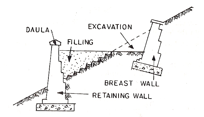
Breast walls:
They are stone walls provided to protect the slopes of cutting in natural ground from the action of weather. The section of wall to be adopted depends upon the height of wall, the nature of the backing and the slope of cutting. The front and back batters of the wall vary from 1 in 4to 1 in 2 (1in horizontal : 4 or 2 vertical), with the minimum top width of 60 cm.
Brick Masonry, Stone Masonry or Plain Concrete Retaining Walls:
These walls are also provided to support earth, loose stone, coal etc. The wall acts as one mass to resist the thrust from the backing and is much more stronger than dry stone masonry wall. The stability of the wall depends entirely upon its dead weight. They are designed on the assumption that masonry or concrete is not subjected to any tensile stresses. In order that the walls may be stable they have to be very thick in section and as such they are seldom constructed for heights beyond 6 m. The top width of masonry walls and concrete walls should not be less than 60 cm. and 45 cm. respectively. The bottom width of the walls varies with the height.
It is necessary to have proper drainage of the retaining wall from consideration of structural safety and stability.
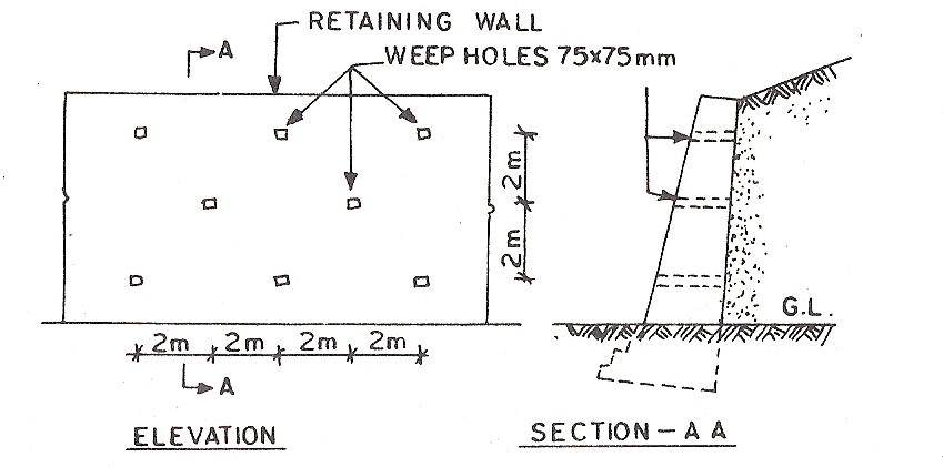
The backing material is drained by providing 50 to 75 mm. square weep holes at every 2 m. c/c vertically and horizontally.
The lowest weep hole is keep 300 mm. above the ground level. In order to prevent blockage of the weep holes, a 450 mm. thick layer of stone chips, gravel or similar granular material should be placed behind the wall right from footing upto its top (covering the full area of the back of wall) simultaneously with the filling of backing material.
Design Of Retaining Walls:
The thrust from the backing which tends to overturn the wall or causes it to slide, is the deciding factor in the selection of the section and type of the wall. There are many conditions upon which thrust exerted by the backing depends, such as cohesion of the soil, dryness of the backing material, the manner in which the material is filled against the wall and so on. There are various theories by the help of which the value of thrust under different conditions can be worked out. Having known the thrust, the section of the wall is so designed that the self weight is sufficient to resist the tendency of the thrust to slide the wall and the bottom width of the wall is such that the resultant force (resultant of the weight of wall and pressure of filling behind) lies within the middle third of the base. This condition is necessary to prevent the tendency of thrust to overturn the wall and to ensure that there is no tension at the wall base. It is equally essential to ascertain that the maximum stress at the toe of the wall does not exceed the safe bearing capacity of the soil.
Calculation of Earth Pressure:
The thrust due to the backfilling, which may be assumed to be earth, is generally calculated by Rankine’s Theory. The theory is based on the assumption that the backing material or earth consists of cohesionless granular particles. The formulae derived from this theory under different conditions of back filling are given below:
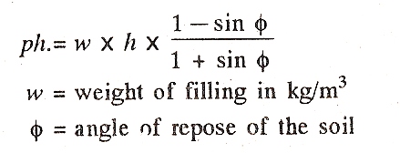
Case 1 : Walls with earth levelled with the top of wall.
(a). Horizontal pressure per sq. m. (ph) at a depth of (h) metre below the levelled top is given by the
formula :
(b). Total horizontal pressure (P) at a depth of (h) metre per metre length of wall is given by the
formula :
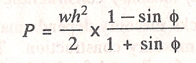
Acting at h/3 metre from the base.
Case 2 : In case of surcharged retaining wall or wall retaining earth filled at slope of a° to the horizontal, the formula giving lateral earth pressure (ph) is given by :
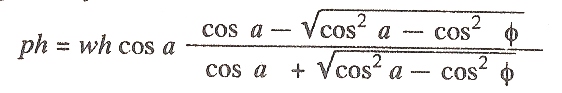
acting parallel to the surcharge slope of the filling.
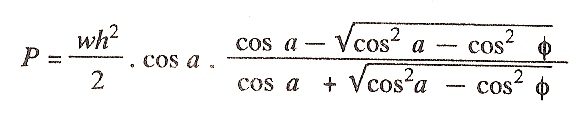
Total pressure (P) at depth of h metre per metre length of wall is given by the formula :
Conditions of Stability of Retaining Walls:
A satisfactory retaining wall must meet the following requirements for ensuring its stability :
(1). The wall should be structurally capable of resisting the pressure applied to it.
(2). The section of the wall should be so proportioned that it will not overturn by the lateral pressure.
(3). The wall should be safe from consideration of sliding, i.e., the wall should not be pushed out by the lateral pressure.
(4). The weight of wall together with the force resulting from the earth pressure acting on it, should not stress its foundation to a value greater than safe bearing capacity of the soil on which it is founded.
(5). It is important to prevent accumulation of water behind a retaining wall. The backing material should be suitably drained by providing weep holes as detailed earlier.
(6). As far as possible, long masonry retaining walls should be provided with expansion joints located at 6 to 9 metre apart.